
What Is Conveying Equipment in an Aggregate Plant?
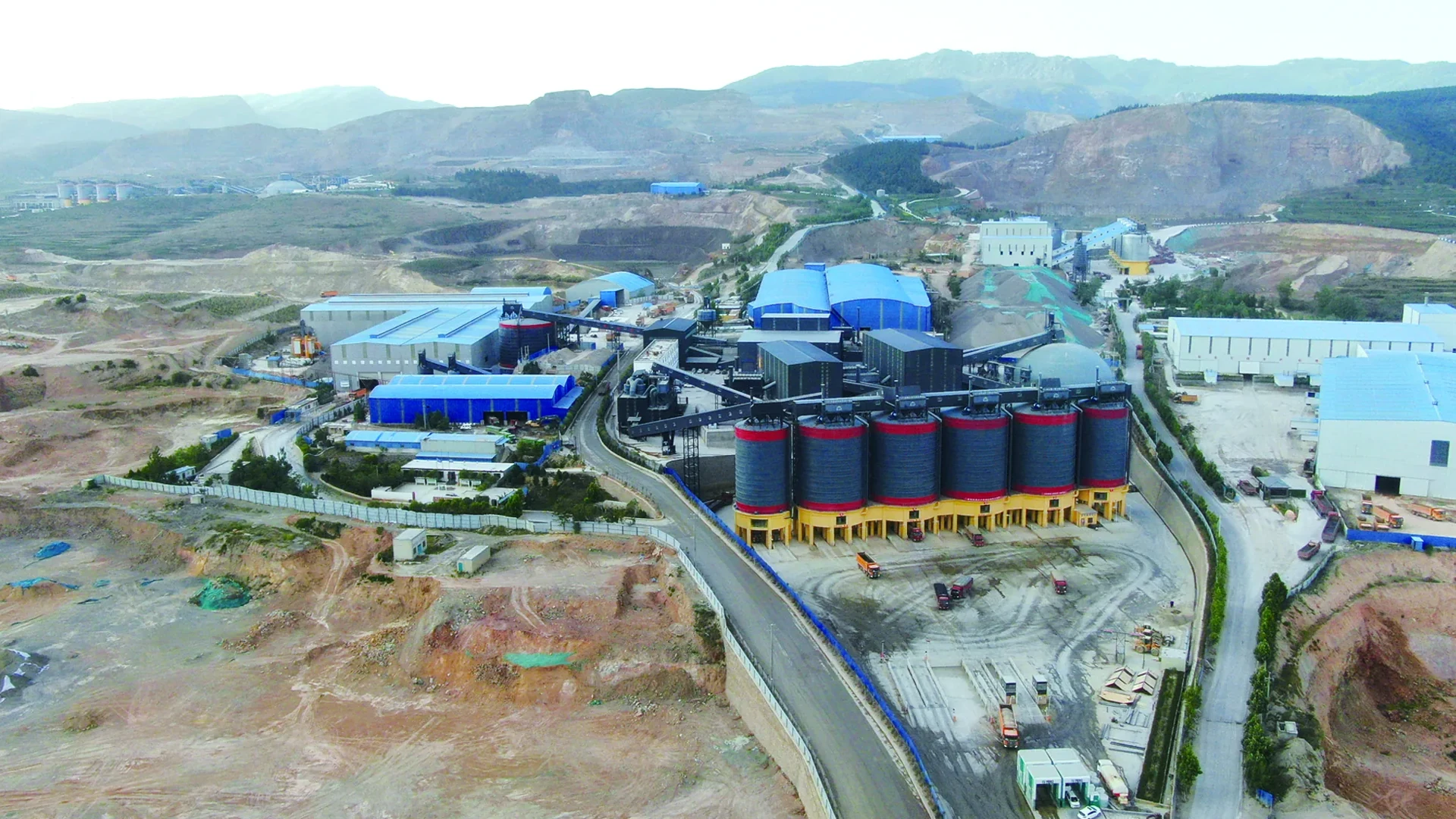
Conveying equipment moves material along a defined route from a loading point to a discharge point. In an aggregate plant, it carries loose stone, gravel and sand between crushers, screens, storage areas and loading facilities. A belt conveyor performs this task with a moving, continuous belt that supports the material during travel.
The complete transfer includes receiving the material, carrying it along the route and delivering it to equipment that can accept the stream. Following that path explains how belt conveyors work, where they fit in a crushing and screening circuit, and why a flow rate needs both material and operating conditions to be meaningful.
What Does Conveying Equipment Do in an Aggregate Plant?
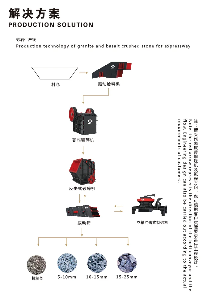
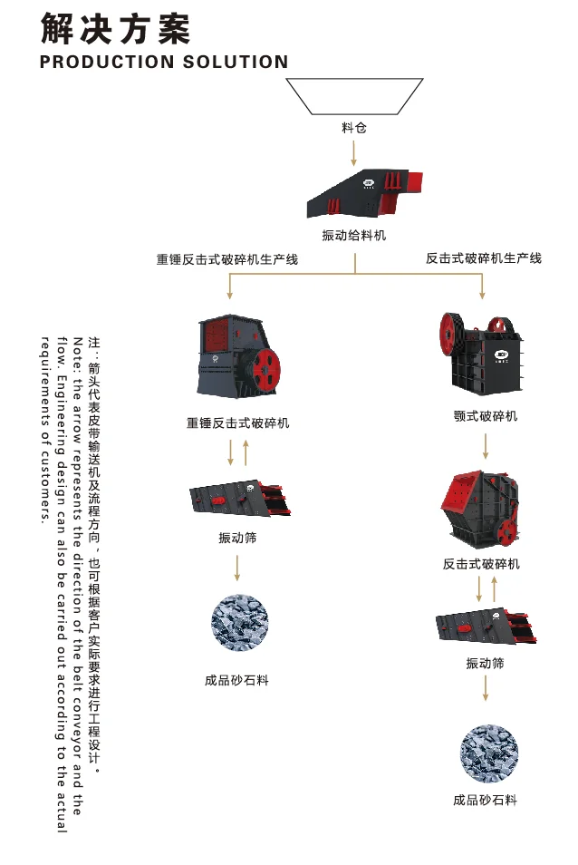
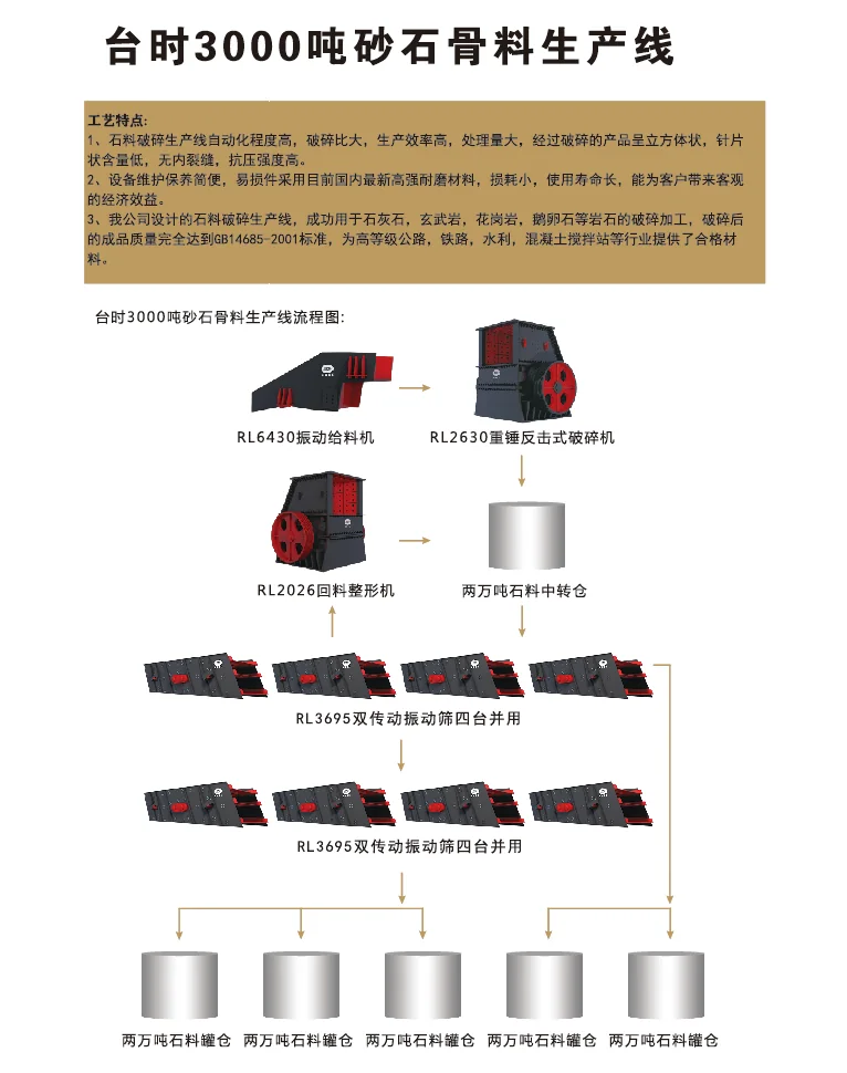
An aggregate production line contains several different tasks. A crusher reduces particle size. A screen separates the resulting feed into discharge streams. Conveying equipment connects these operations by transporting each stream to its next destination.
Bulk material conveying equipment handles many loose particles together as a continuous or intermittent stream. Its duties change through the plant. A conveyor receiving freshly crushed stone handles a different particle-size distribution from one carrying screened sand, even when both belong to the same production line.
A conveyor’s role therefore includes its origin and destination. “Crusher discharge to screen feed” identifies a useful process connection: it explains what material arrives, which downstream operation receives it and whether the transfer belongs to a forward-processing, return or finished-product route.
Transfer conveyors connect process stages, while overland arrangements can carry material over longer routes. The distance and layout change, but the central task remains moving a defined material stream between locations.
How Does a Belt Conveyor Move Bulk Material?
The Carrying Run and the Return Run
A belt conveyor uses an endless belt arranged around pulleys. Material enters the carrying run, travels with the moving belt and leaves at the discharge. The unloaded belt then follows the return run back toward the loading end, completing the circuit.
On a conventional troughed aggregate conveyor, carrying idlers support the belt in a shape that helps contain the loose material. Return idlers support the belt on its way back. The belt’s return run is part of the conveyor’s mechanical loop; it should not be confused with a separate conveyor carrying stone back to a crusher.
Drive, Pulleys, Idlers and Take-up
The drive unit supplies power to a drive pulley. Contact between the pulley and belt transmits the force that moves the belt. Idlers provide rolling support along the route; they do not perform the drive pulley’s main powered function.
The main components of belt conveying equipment work together as follows:
| Component | Function in the conveying process |
|---|---|
| Conveyor belt | Provides the moving surface that carries the material |
| Motor and drive unit | Supply the mechanical power needed to move the belt and its load |
| Drive pulley | Transfers driving force to the belt through contact with its surface |
| Terminal and bend pulleys | Guide the belt around the ends or other changes in its path |
| Carrying and return idlers | Support the loaded and returning sections of belt |
| Take-up or tensioning device | Maintains the working tension required by the conveyor arrangement |
| Supporting frame | Holds the components in their planned positions along the route |
Working tension must suit the design: increasing it without considering the belt, pulleys and structure is not a general way to increase conveying capacity.
The RION belt conveyor range includes B500, B650, B800, B1000, B1200, B1400, B1600, B1800, B2000 and B2200, with gallery-type and open-type layouts.
Where Are Conveyors Used in a Crushing and Screening Circuit?
Process Transfers, Return Material and Product Stockpiles
Consider a hypothetical circuit in which crushed stone travels to a screen, one discharge returns for further crushing, and other discharges travel to separate product stockpiles. Each conveyor carries a particular stream, so its place in the circuit explains its duty.
| Starting point | Destination | Material stream | Conveying duty |
|---|---|---|---|
| Crusher discharge | Screen feed point | Crushed material awaiting classification | Connect reduction and screening stages. |
| Selected screen discharge | Further crushing stage | Material assigned to additional reduction | Complete the return route in a closed circuit. |
| Product screen discharge | Designated stockpile or bin | A separated aggregate product | Keep that product on its intended storage route. |
| Storage discharge | Loading point or another plant section | Material released for the next operation | Transfer the released stream to its destination. |
Some plants use an open circuit without a return-crushing route. Others divide material among more stages or combine streams where the process requires it.
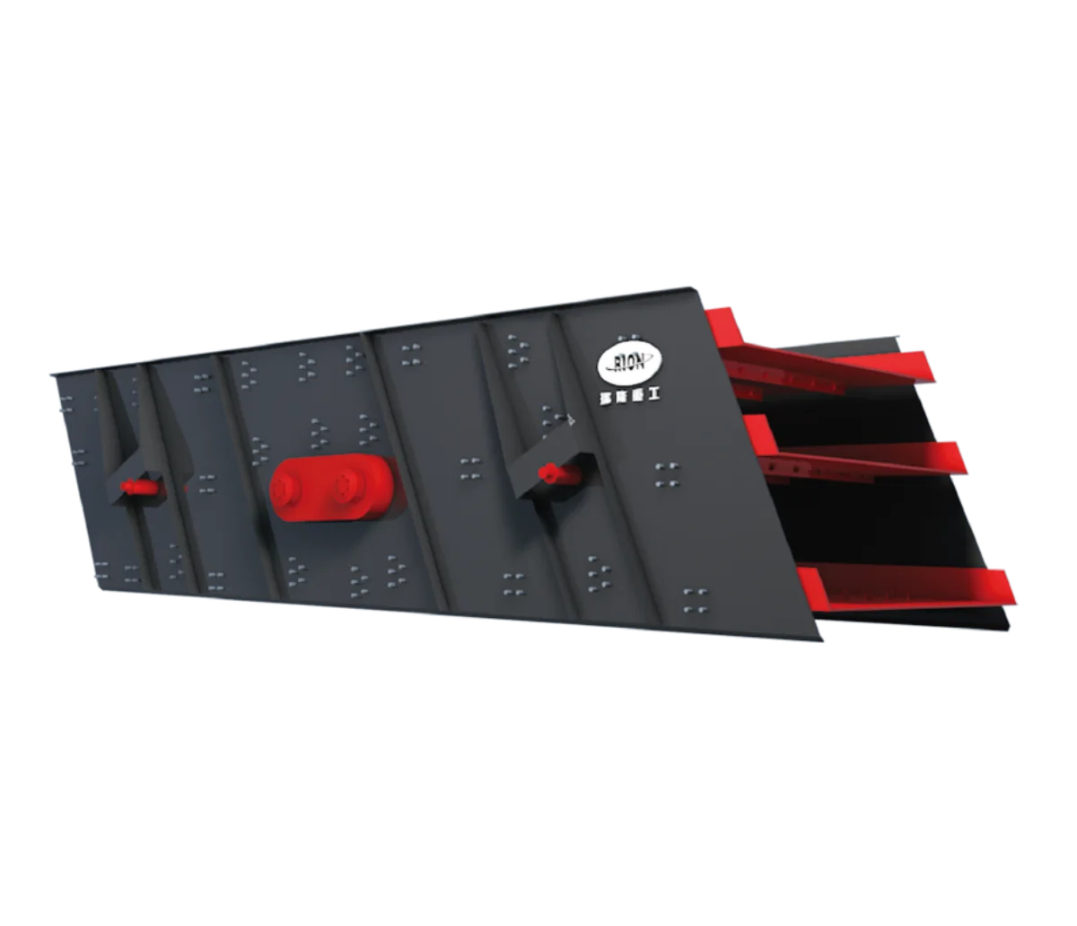
The screen creates the discharge streams, and the conveyor arrangement determines where they travel. For example, vibrating screens for aggregate grading can connect to product-transfer and crusher-return routes. Product grading comes from the crushing and screening process; the conveyor then directs that stream to its assigned stockpile.
Feeder and Conveyor Duties
A feeder supplies material to receiving equipment at a rate suited to the process. A conveyor provides a transport route. These duties can overlap: a belt feeder uses a moving belt for controlled delivery, and some belt-based systems also measure or regulate flow when equipped for that purpose.
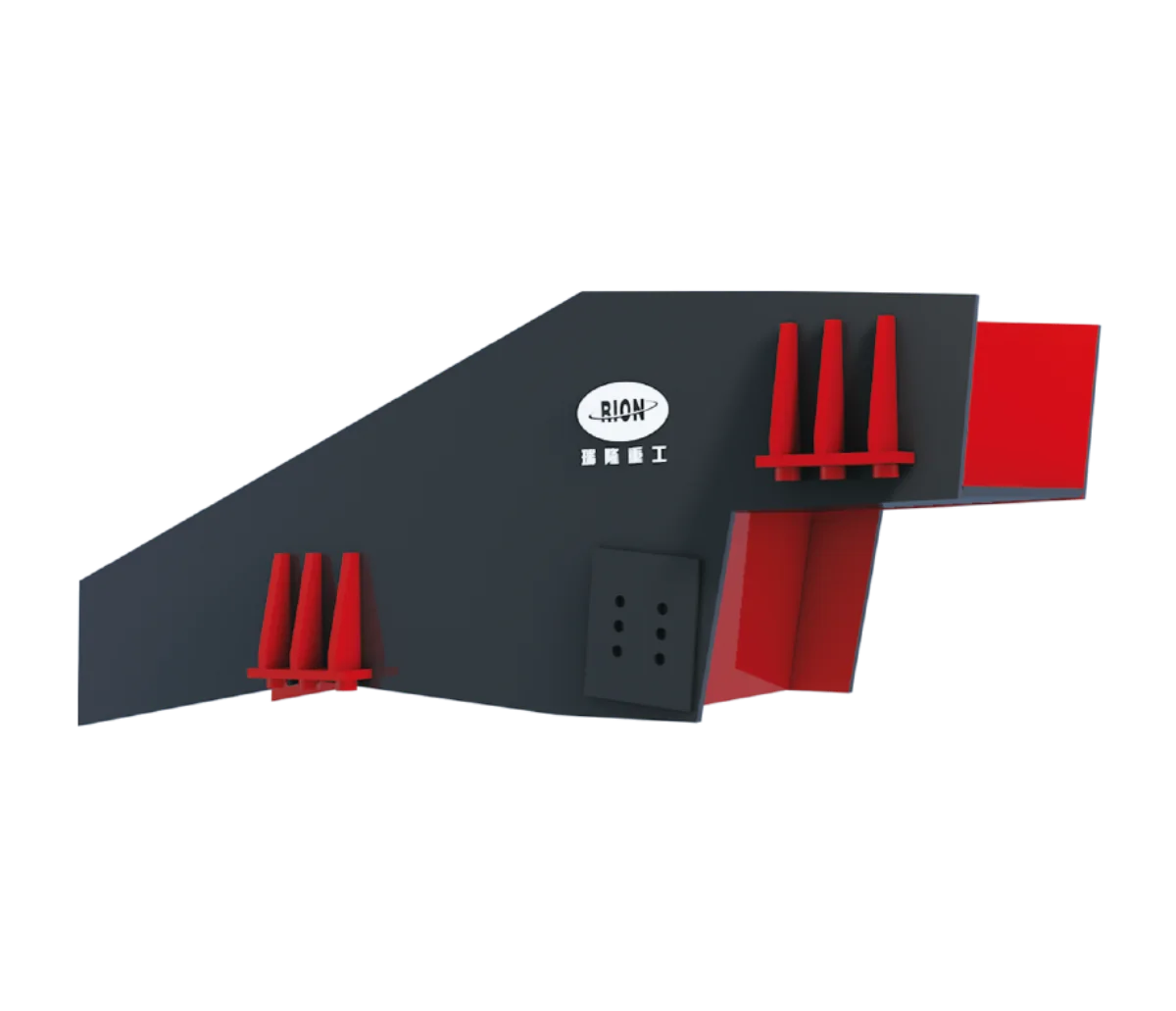
For a different feeding mechanism, RION’s vibrating feeders for controlled plant feeding use a trough and excitation arrangement to move material toward a crusher or another receiving stage. This illustrates why equipment should be understood through both its mechanism and assigned duty. A transfer conveyor receiving the feeder’s output does not automatically perform the same control function.
Why Can’t Belt Width Alone Define Conveyor Capacity?
Volume Flow and Bulk Density
Volume flow describes how much space the conveyed material occupies per unit of time. Mass flow describes how much material mass passes per unit of time. The relationship is:
Mass flow (t/h) = volume flow (m³/h) × bulk density (t/m³)
Here, t means a metric tonne, equal to 1,000 kg. The density must be bulk density, which relates mass to the volume occupied by the loose material, including spaces between particles. The density of the solid mineral itself is a different quantity.
Consider two purely hypothetical calculations:
| Assumed actual volume flow | Assumed bulk density | Calculated mass flow |
|---|---|---|
| 250 m³/h | 1.6 t/m³ | 400 t/h |
| 250 m³/h | 1.2 t/m³ | 300 t/h |
At the same actual volume flow of 250 m³/h, the higher bulk density gives a higher mass flow because each cubic metre contains more mass. These calculations convert volume flow to mass flow; a capacity rating also requires the conveyor’s loading, speed and design conditions. If loading changes with the material, the volume flow changes as well.
Belt Speed, Loading and Route Conditions
Belt width contributes to the space available for carrying material, but the actual loaded cross-section and belt speed also affect volume flow. A series designation by itself cannot describe these operating conditions. Particle size, loading pattern and the belt’s carrying shape influence how that space is used.
The route adds further conditions. An inclined transfer, a longer run and a different discharge elevation require consideration of the complete conveying arrangement. Receiving equipment must also accommodate the delivered stream. A mass-flow conversion cannot establish whether the drive, belt and structural arrangement are suitable for that duty. RION’s conveyor selection information similarly connects capacity assessment with material, speed, inclination and route conditions.
It also helps to distinguish actual flow from rated capacity. Actual flow describes the material passing during a stated period. A capacity figure describes an equipment capability under specified conditions. An average hourly flow can conceal short periods of heavier loading, so the operating time basis matters when comparing the two.
Why Do Loading and Discharge Points Matter?
How Material Enters and Leaves the Belt
The loading point joins two different movements: the incoming material follows a chute or upstream discharge, while the receiving belt moves along its own route. Their directions, relative positions and height difference determine how the material reaches the carrying surface.
Material entering centrally can be distributed around the belt’s intended carrying path. A stream arriving heavily to one side places a different load on the belt and its support. The loading zone also needs to support the receiving belt and contain loose particles as they settle into the moving load.
Martin Engineering’s Load Your Cargo Correctly describes preparing the belt for loading, including stabilizing and centering its path, forming the carrying profile and sealing the load zone. These principles explain why a moving belt alone is only part of a functioning material-transfer interface.
At discharge, the question reverses: where will the leaving stream land? The receiving chute, screen, conveyor or storage point must be positioned for that stream and able to accept it. A transfer into a screen, for instance, needs to align with its feed arrangement so the delivered material can be distributed across the intended screening area.
Matching the Conveyor to the Receiving Equipment
An illustrative crusher-to-screen transfer brings these relationships together. The crusher’s discharge establishes the upstream connection, the conveyor carries that output across the required distance and elevation, and the screen’s feed arrangement defines the receiving interface. Understanding one component requires understanding these adjacent connections.
Four descriptions make the duty clear:
- Route: the loading and discharge locations, transfer distance and elevation change.
- Material: particle size, bulk density and moisture condition.
- Flow: the actual operating rate and expected peaks.
- Receiving equipment: the next machine, chute, storage point or loading facility.
Together, they explain what the conveyor must transport and how the transfer should fit into the process.
For an aggregate project, you can discuss your material transfer layout with RION using those four descriptions. They provide a practical connection between the basic conveying principle and the conditions of the production line.