
Where Should Buffer Storage Be Placed in a Crushing Equipment Circuit?
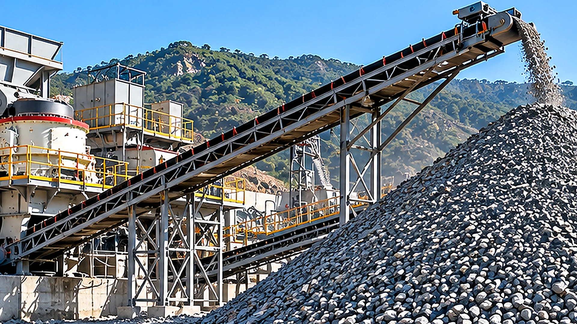
A buffer stockpile or surge bin is usually most valuable at the point where one crushing stage must operate independently of the next. In a conventional stationary aggregate plant, this is often between primary crushing and the downstream secondary crushing and screening circuit. The purpose is not simply to store rock. It is to absorb temporary differences in material flow while allowing downstream equipment to receive a more consistent feed.
However, adding storage between every crusher is neither necessary nor economical. The correct location and usable capacity depend on actual production fluctuations, material characteristics, reclaim arrangements and plant operating schedules.
For quarry operators evaluating crushing equipment layouts, the key engineering question is therefore not how large a stockpile can be constructed, but how much live, recoverable material is needed to keep the next processing stage operating under realistic conditions.
Why Do Crushing Stages Need Buffering?
Intermittent Primary Crusher Discharge
Primary crushing rarely produces an identical material flow every minute. In a quarry supplied by haul trucks, the primary crusher receives material in batches. The rate of material entering the crusher depends on truck arrival intervals, dumping time, rock fragmentation, maximum lump size and the amount of material already in the feed hopper.
Even when a primary jaw crusher has adequate nominal capacity, large rock fragments can temporarily reduce throughput. Feed interruptions, inspection stops and changes in feed gradation can also affect the discharge rate. These fluctuations do not necessarily indicate poor crusher performance. They are often normal characteristics of the upstream mining and primary crushing operation.
A primary crusher may therefore deliver a high average throughput over a shift while its instantaneous discharge rate varies considerably. If that material is transferred directly to a secondary crusher, every significant interruption or surge in the primary stage can influence downstream operation.
Secondary Crusher and Screen Feed Requirements
Secondary crushing and screening are generally easier to control when feed arrives at a relatively stable rate and within the equipment’s operating limits. An underfed secondary crusher may operate below its intended loading conditions. Excessive or uneven feed can cause overloading, unstable chamber conditions or material accumulation at transfer points. The particular consequences depend on crusher design and operating mode.
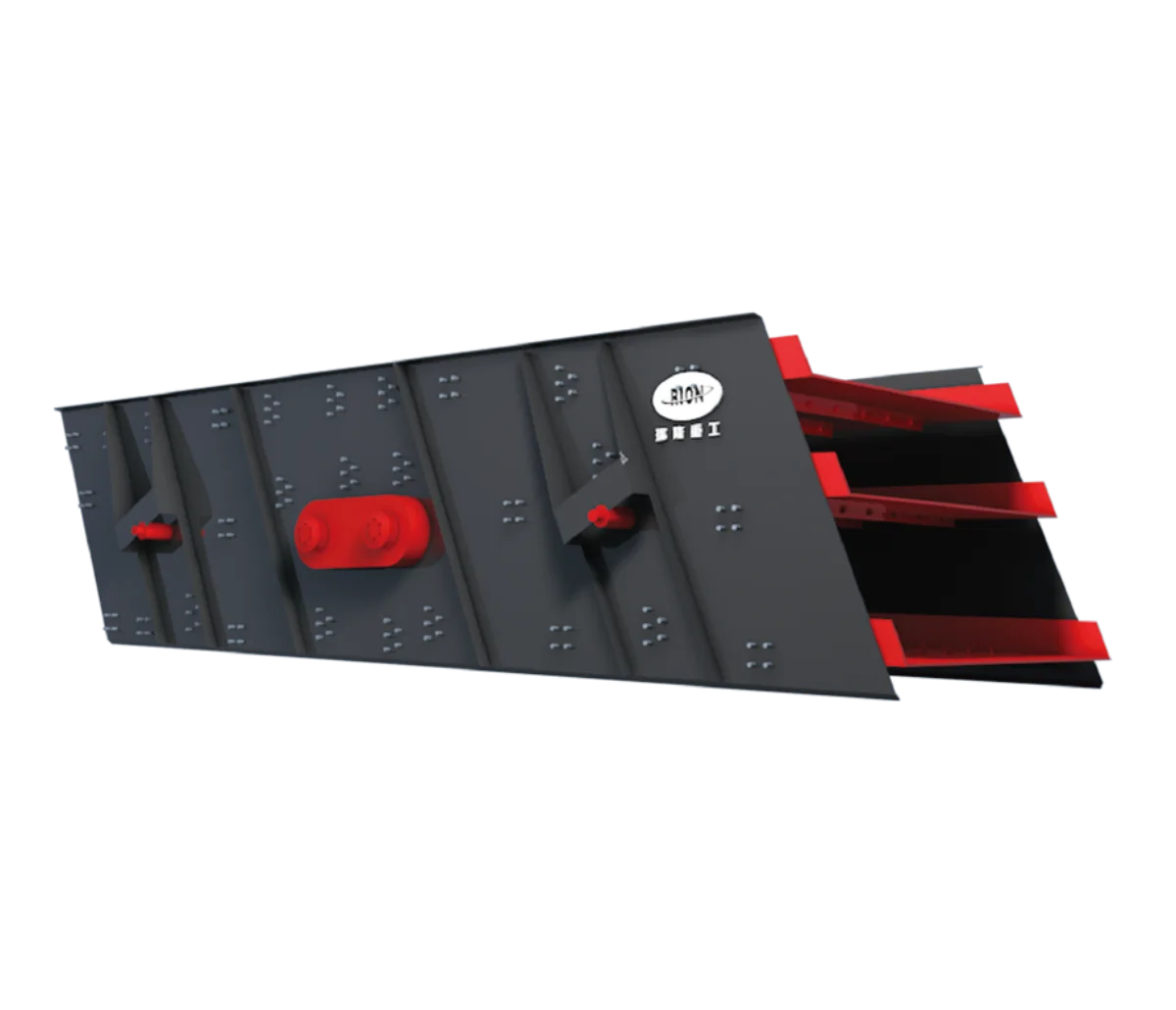
Screens are also sensitive to changes in loading. A sudden increase in feed can deepen the material bed, reduce effective separation opportunities and increase the load returning through a closed crushing circuit. A buffer placed between the primary and downstream stages creates an opportunity to regulate these fluctuations.
Material can accumulate temporarily when the primary stage produces more than the downstream circuit consumes. During short primary interruptions, stored material can continue feeding the secondary system. This separation of operating rates is one reason surge storage is frequently considered in stationary aggregate plant design.
Short-Term Fluctuations Versus Permanent Bottlenecks
A buffer cannot correct a sustained capacity mismatch. For example, if the primary stage continuously delivers 500 tonnes per hour while the downstream circuit can process only 400 tonnes per hour, storage will accumulate material at a net rate of 100 tonnes per hour until its available capacity is exhausted. The buffer may postpone the problem, but it does not eliminate it.
By contrast, if the primary crusher intermittently produces 500 tonnes per hour while the downstream system requires 400 tonnes per hour, temporary storage may allow both sections to operate at different rates for a limited period, provided their overall operating schedules and material balance are compatible. This distinction should be established before purchasing additional equipment or allocating space for a stockpile.
Where Should a Surge Pile or Surge Bin Be Located?
Between Primary and Secondary Crushing
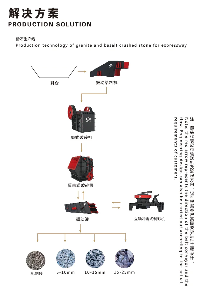
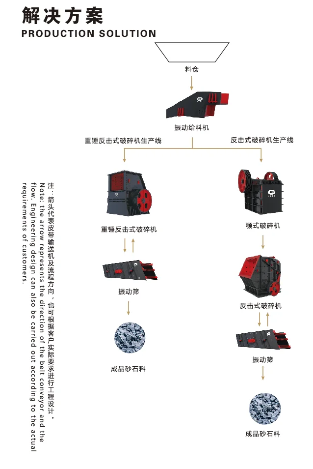
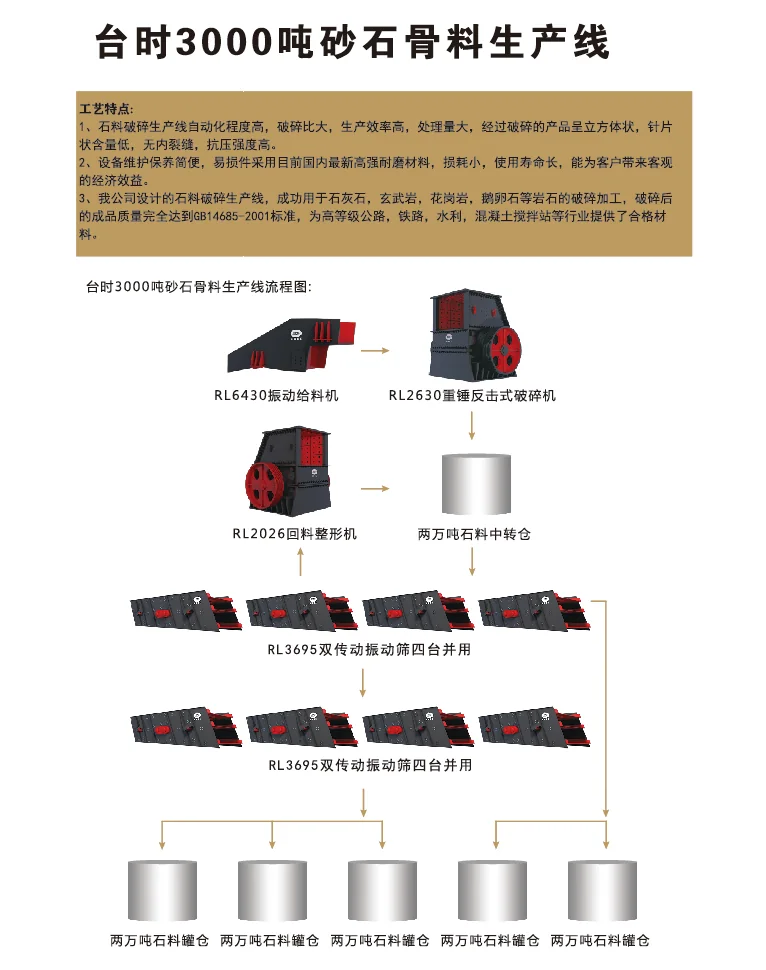
For many stationary quarry configurations, the discharge side of the primary crusher is a logical location for intermediate storage. A typical arrangement can be described as: primary crusher → transfer conveyor → surge pile → reclaim feeder → secondary crushing circuit → screening.
In this layout, primary crushing can continue during certain downstream interruptions until the permitted storage level is reached. Conversely, secondary processing can continue during a short primary stoppage while recoverable material remains available. The arrangement also allows the primary and secondary sections to operate on different schedules when the production plan and available storage support this approach.
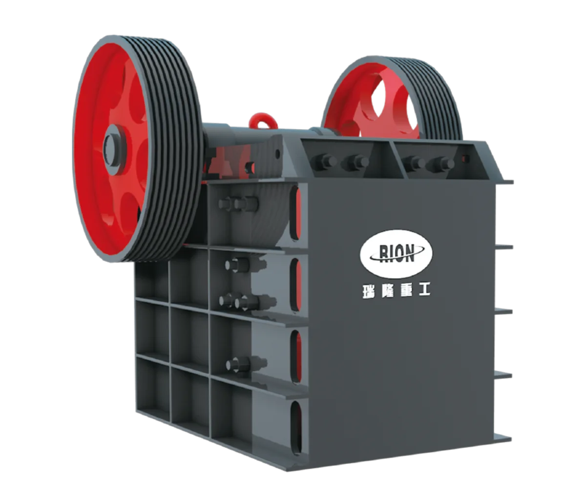
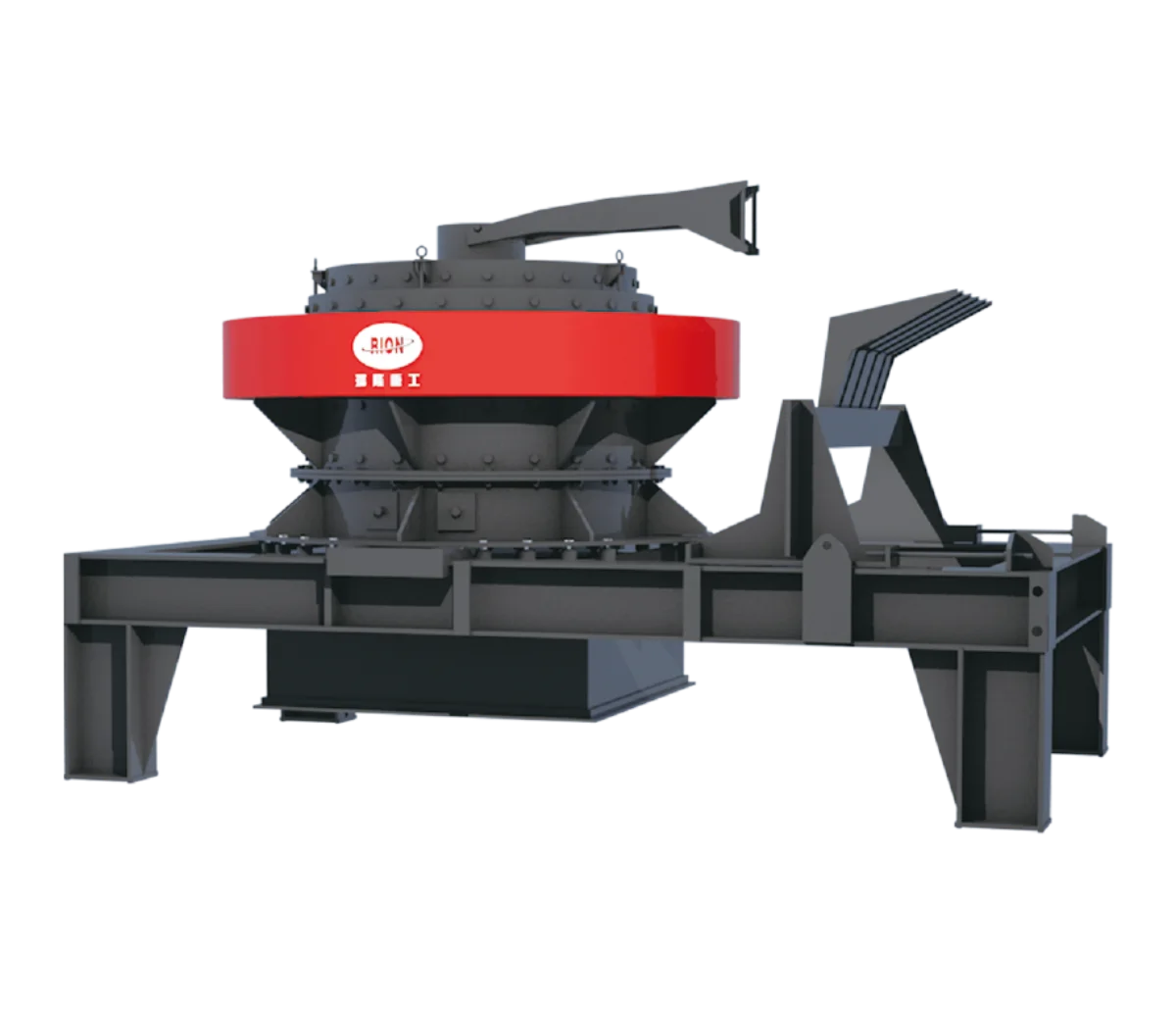
The technical benefit comes from separating two operating stages with different flow characteristics, rather than from the stockpile itself. For an equipment portfolio such as RION’s, this interface may involve a primary Jaw Crusher, an intermediate stockpile and downstream Cone Crusher equipment. Actual arrangements should be determined by the material, crusher duties, feed sizes and project layout rather than assuming this sequence suits every plant.
Before Secondary Screening or Tertiary Crushing
Additional intermediate storage may be useful where a later processing stage experiences significant operational interruptions or variable feed demand. However, placing a buffer farther downstream changes which equipment remains exposed to upstream fluctuations.
For example, a pile located after secondary crushing does not isolate the secondary crusher from irregular primary discharge. The secondary crusher must still accommodate the upstream operating pattern. This can be important when comparing two layouts that appear similar in total equipment capacity.
A surge bin before tertiary crushing may help regulate feed to the final reduction stage, but its value depends on the surrounding screening circuit, return-load behaviour and available control arrangements. Storage position should therefore be selected by identifying the specific stages that need to operate independently.
Process Buffers Versus Finished Aggregate Stockpiles
A surge pile should not be confused with a finished product stockpile. A process buffer normally stores material that still requires crushing, screening or another processing operation. Its function is to support continuity and control the movement of material through the plant.
A finished aggregate stockpile holds material that has already met the intended product classification and is awaiting loading, blending or dispatch. These different purposes affect layout design. A process stockpile requires dependable reclaim capacity and close coordination with downstream equipment. A finished stockpile is more strongly influenced by inventory, product segregation, truck loading and shipment requirements.
Treating both as ordinary storage capacity can lead to incorrect assumptions about the amount of material actually available to support production.
How Much Live Storage Capacity Is Required?
Estimating Material Accumulation from Flow Differences
A preliminary storage assessment begins with the mass balance across the buffer. For a defined operating period: Change in stored mass = Material entering storage − Material leaving storage.
If both flows are assumed constant over that period, the relationship becomes ΔM = (Qin − Qout) × t, where ΔM is the change in stored mass in tonnes; Qin and Qout are the incoming and outgoing mass flow rates in tonnes per hour; and t is the duration in hours.
Consider an illustrative case in which a downstream crushing circuit consumes 350 tonnes per hour and the primary crusher stops feeding the buffer for 20 minutes. If the downstream circuit is expected to continue operating at the same rate, the amount withdrawn during the interruption is approximately 350 × (20/60) = 116.7 tonnes.
This means at least approximately 117 tonnes of usable stored material would be required solely to bridge that particular interruption, assuming uninterrupted reclaim and no other losses or restrictions. It is not a recommended buffer capacity for a real RION installation. It is a calculation example showing how interruption duration and downstream demand influence the mass of material needed.
A working design must also consider repeated interruptions, expected starting inventory, future replenishment, allowable storage levels and appropriate operating reserves. When flow rates vary substantially over time, calculations should use the complete material-flow history rather than a single average.
Live Reclaimable Capacity Versus Total Stockpile Volume
A stockpile containing 1,000 tonnes does not necessarily provide 1,000 tonnes of usable surge capacity. Live storage is the portion of the material that can be recovered through the installed reclaim arrangement under the intended operating conditions. Material outside the effective withdrawal zone may remain in the pile unless a loader or another reclaim method moves it.
A stockpile with a single reclaim point may therefore have a much lower live-storage fraction than a suitably designed system with multiple withdrawal locations. The fraction depends on pile geometry, repose angle, feeder arrangement, discharge characteristics and the material’s flow behaviour.
The plant designer must distinguish total physical storage, material that can be recovered through the planned operating method, minimum inventory required for stable reclaim, and operational storage available between allowable low and high levels. It is the operationally usable portion that matters when estimating how long downstream equipment can continue running.
Storage Duration and Operating Variability
A fixed rule such as providing a certain number of minutes or hours of stockpile capacity may be useful for initial discussion, but it cannot replace an assessment of actual plant operations. Relevant questions include how often primary feed stops, how long interruptions normally last, whether downstream processing continues during maintenance and whether the primary stage operates on the same shift schedule.
The buffer must also be replenished. If the primary crusher cannot produce enough material during available operating hours to replace downstream consumption, increasing the pile capacity will not establish a sustainable operating arrangement. Storage sizing should consider both the amount of material required during interruptions and the ability to restore inventory afterward.
How Should Reclaim Feeders and Conveyors Be Integrated?
Reclaim Feed Rate Control
A stockpile does not automatically produce a controlled discharge. Material must be withdrawn through a reclaim system suited to the stored rock size, bulk density, moisture, abrasiveness and required feed rate. Depending on the arrangement, this may involve feeders positioned below a surge bin or at designated withdrawal points beneath a stockpile.
The feeder should operate within its approved loading and discharge limits while delivering the flow required by the receiving circuit. RION’s Vibrating Feeder product range provides a relevant equipment category for discussing controlled material feed in aggregate processing.
However, suitability for a specific reclaim installation requires engineering confirmation. A feeder suitable for a conventional receiving hopper should not automatically be assumed appropriate for every high-head stockpile reclaim condition. Particular attention is needed where fine material, moisture or irregular rock shapes increase the possibility of bridging, blockage or uneven discharge.
Matching Conveyor Capacity to Crusher Demand
The reclaim conveyor must accommodate the intended material flow, including realistic operating variation. Conveyor suitability depends on more than belt width. Belt speed, material bulk density, trough configuration, incline, lump size, loading geometry and transfer-chute design all influence effective carrying capacity.
A conveyor that nominally handles the required average tonnage may still experience difficulties if a reclaim feeder produces short periods of excessive loading. Likewise, a correctly sized conveyor may perform poorly if material enters off-centre or creates excessive impact at the loading point.
The Belt Conveyor category is therefore an important interface between storage and downstream processing. For reliable operation, the reclaim feeder, transfer chute, conveyor and receiving crusher should be evaluated as one material-handling system.
Material Segregation, Blockage and Discharge Conditions
Coarse aggregate does not always remain uniformly mixed while being stacked and reclaimed. During stockpile formation, larger particles may travel farther down a slope while smaller particles accumulate in different regions. The extent of this segregation depends on the material gradation and stacking method.
If the reclaim system draws predominantly from one region, the downstream crusher may receive a feed distribution that differs from the original primary-crusher discharge. Changes in feed grading can influence crusher loading and screening performance.
The designer should consider stacking geometry, conveyor discharge position, withdrawal-point arrangement and whether the recovered material will remain sufficiently representative. Access for inspection, maintenance and safe intervention is another requirement. Stockpile reclaim areas can present serious hazards, including buried equipment, confined access, unstable material and unexpected movement. Reclaim-system design, guarding and maintenance procedures must be assessed for the actual installation.
When Is Intermediate Buffer Storage Unnecessary?
Direct-Feed Layouts with Stable Material Flow
Not every crushing plant needs a separate surge pile. A compact operation with relatively stable material supply, compatible equipment capacities and suitable control arrangements may be able to transfer material directly between crushing stages. This can reduce the number of handling points and simplify the plant footprint.
However, a direct-feed layout means interruptions in one section can affect connected equipment more immediately. The choice involves balancing operational flexibility against equipment, land and handling requirements.
Space, Dust and Additional Handling Requirements
A buffer stockpile occupies space and may require additional conveyors, support structures, reclaim equipment, electrical installations and maintenance access. Open stockpiles also introduce environmental considerations related to windblown dust, surface runoff and material containment.
Enclosed surge bins can reduce some exposure issues but introduce their own structural, access and material-flow requirements. These consequences should be considered alongside any expected operational improvement. For a restricted site, a smaller buffer or a different plant arrangement may be more practical than a large intermediate stockpile.
Why Storage Cannot Remove a Permanent Bottleneck
A common design mistake is adding storage to compensate for a downstream system that is consistently undersized. If the downstream crushers and screens cannot process the required long-term production rate, stored material will continue accumulating whenever upstream production exceeds downstream capacity.
The correct response may instead involve reviewing crusher duty, screen capacity, circulating load, material characteristics or planned production targets. Buffer storage should be justified by the pattern of operating variation, not used as a substitute for verifying the capacities of the connected equipment.
What Data Should Buyers Review Before Finalizing the Layout?
Feed Size, Material Properties and Throughput Records
A useful engineering assessment begins with representative material data.
| Required information | Why it matters |
|---|---|
| Maximum lump size and feed gradation | Influences chute clearances, feeder design and flow behaviour |
| Bulk density | Converts stored volume into approximate material mass |
| Moisture and fine-particle content | Helps assess adhesion, blockage and reclaim difficulties |
| Primary crusher discharge history | Identifies production fluctuations and interruptions |
| Downstream circuit demand | Determines withdrawal requirements and buffer depletion |
| Available storage area and geometry | Constrains stockpile or bin configuration |
Single-point nominal capacity figures are less informative than operating records that show variation during a representative shift.
Operating Schedule and Production Fluctuations
The plant’s operating schedule should be examined together with material flow. A primary crushing section operating for fewer hours than the downstream plant may require sufficient production rate and storage to support the difference in schedules.
Maintenance practices also matter. A planned shutdown that requires downstream equipment to operate independently has different storage implications from an occasional short interruption. Where reliable production data are unavailable, the project team should identify the assumptions used for preliminary calculations and test how sensitive the result is to those assumptions.
Reclaim Layout, Site Constraints and Safety Requirements
Before the layout is finalized, the project team should review stockpile location, reclaim access, structural requirements, environmental controls and emergency maintenance arrangements. The layout must also account for any required separation between mobile equipment and personnel working near conveyors or reclaim systems.
RION’s Aggregate Production Solution covers the broader context of matching crushing, screening and material-handling equipment within an aggregate plant.
Buyers discussing a proposed circuit can provide RION with the rock type, target throughput, product grading, operating schedule, equipment configuration and available site footprint through the project enquiry page.
The central design principle remains straightforward: place buffer storage where it provides a measurable operational separation between processing stages, and size it according to recoverable material and realistic operating variation.
A properly evaluated buffer can support more consistent downstream operation. An incorrectly located or oversized stockpile may simply add handling complexity without resolving the plant’s real limitation.